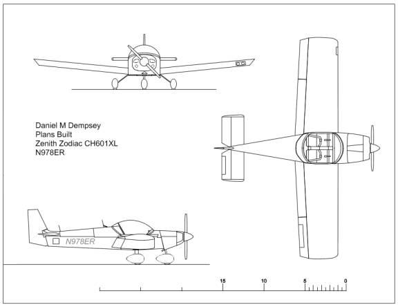
Builder: Daniel Dempsey
Number N978ER
Serial Number 1
December 02, 2013
This is the
original draft of this manual produced
before the airplane has been flown.
Table of Contents
Zodiac CH 601 XLB – Aircraft Data
Airspeed Calibration Table in Knots
(Flaps Up)
Airspeed Calibration Table in Knots
(Flaps Down)
Engine Failure In Flight (Restart Procedure)
Power Off Landing (assumes off runway)
Precautionary Off Runway Landing
Electrical Power System Malfunctions
Volt Meter shows excessive voltage
Amplified Emergency Procedures
Engine Failure In Flight (Restart
Procedure)
Inside Airplane Pre-Flight Inspection
Zodiac CH 601 XLB – Aircraft Data
Aircraft Type: Plans Built Zodiac CH 601 XLB
Category: Single Engine Land
Designer: Chris Heinz of Zenith Aircraft Company
Builder: Daniel Dempsey
1051 Hopkins Court
Charlottesville VA, 22901
Years of Construction: 2005->2013
Registration Number: N978ER
Aircraft Serial Number: 1
Plans Serial Number: 54
Plans Date 2003
Power Plant Corvair Conversion
Engine Serial Number T091RH
Propeller Hand Carved by Builder
Date of Manufacture 08/08/2013
Introduction
This manual describes the proper operation of the plans built Zodiac 601 XLB constructed by Daniel Dempsey between Spring 2005 and August 2013.
This aircraft is intended to be flown by competent experienced pilots after familiarization with the contents of these instructions. The pilot of this aircraft should be thoroughly familiar with the operating limitations, normal and emergency procedures from this manual.
For maintenance instructions see the Maintenance Manual.
For operating or service updates see the Zenith website at: http://www.zenithair.com/zodiac/xl/index.html
WARNING: Operating this aircraft outside of its operational limitations can lead to death of the pilot, passengers and those on the ground. So DON”T DO IT.
Background Information
Airframe
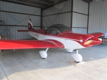
The
airplane is a Zenith Zodiac CH601XLB designed by Chris Heinz and built from
plans. The Zodiac is a two place low
wing all metal aircraft. The CH601XL
has a few unusual design features, such as the all-flying rudder and the
flexible aileron hinges, but is otherwise a very conventional light aircraft. I built the aircraft in our family living
room while living in Nelson County Virginia.
The plans were purchased in 2004 and construction was begun in
2005. Construction was completed in the
Fall of 2013. The aircraft has the
structural upgrade kit applied that came out in December of 2009. I made all the fiberglass parts other than
the spinner. The nose bowl and cowling
are of my own design. The aircraft is
equipped with the long range fuel capacity option.
Engine
The
airplane is powered by a Corvair auto conversion that was also built by
me. The engine core was from a 1967
Chevrolet Corvair automobile. This car
sported a 6 cylinder air cooled boxer that put out 110 horse power. The Corvair auto conversion was done using
a conversion manual authored by William Wynne.
The conversion provides 100 HP using a direct drive (no reduction gear)
to the propeller. I made the parts to
do the conversion in my father’s machine shop in Rustburg Virginia. The engine uses a fifth bearing upgrade to
the engine purchased from Dan Wessman.
I replaced his adjustable centering crankshaft extension with a single
piece extension of my own design. I made the engine mount by making slight
modifications to the mounts shown for other engines in the Zenith plans. The carburetor is from a 1957 MGA
automobile.
Propeller
I also
made the propeller for this airplane.
The propeller is 58” in diameter and has a 56” pitch at the tips. The pitch is reduced as it gets close to the
spinner. The propeller is carved from
birch laid up from (5) ¾” thick planks and glued with resourcenol glue. This gives an overall thickness of 3 and ½
inches. The spinner is a 13” Van’s spinner.
Plans Modifications
A few
minor departures were made from the plans.
The skins
are dimpled and flat head rivets used on all skins. The plans did not call for this refinement.
I used a
landing gear sold by Aircraft Spruce as a CH601XL landing gear, but nothing
like the one in the plans. The gear I
purchased came from an Eastern European company and I understand these are
popular in Zodiacs throughout Europe.
It is made of composite (not aluminum as in the plans) and is not a
single piece like in the plans but 2 separate legs. I beefed up the main gear tunnel and designed and made a set of
inner brackets to adapt this gear.
The plans
called for an electrically actuated flap lever. This plane is using a mechanical one of my own design.
The fuel
tanks were not welded as called for in the plans but are riveted and sealed
with Proseal.
General Information
Drawings
Specifications
|
ZODIAC CH601 XLB |
Corvair (100 hp) |
|
|
|
WING SPAN |
27 FT. |
8.23 m. |
|
|
WING AREA |
132 SQ. FT. |
12.3 m.sq. |
|
|
LENGTH
|
20 FT. |
6.1 m. |
|
|
HORIZONTAL
TAIL SPAN |
7 FT. 7 IN. |
2.30 m. |
|
|
RUDDER
TIP HEIGHT |
6 FT. 6 IN. |
1.98 m. |
|
|
EMPTY
WEIGHT |
690 LB. |
312 kg. |
|
|
USEFUL
LOAD |
650 LB. |
294 kg. |
|
|
GROSS WEIGHT |
1,320 LB. |
595 kg. |
|
|
WING
LOADING |
9.85 psf |
48 kg/sq.m. |
|
|
FUEL
CAPACITY (wing tanks) |
= 48 Gal. (US) |
2 x 46 l. |
|
|
POWER
LOADING |
13 LB./HP |
5.9 kg/HP |
|
|
CABIN
WIDTH |
44 INCHES |
112 cm. |
|
|
PROPELLER
(fixed pitch, wood) |
58 INCHES |
285 cm |
|
|
LOAD
FACTOR (G) ultimate * |
+ 6 / - 4 g |
|
|
Performance
|
PERFORMANCE |
Corvair Conversion |
|
|
ZODIAC CH601 XLB |
Gross Weight |
Gross Weight |
|
MAX
CRUISE (sea level, continuous) |
134 mph |
216 km/h |
|
75%
CRUISE @ 8,000 ft. (TAS*) |
155 mph |
250 km/h |
|
VNE |
160 mph |
260 km/h |
|
Vs1 STALL SPEED – no flaps |
51 mph |
82 km/h |
|
Vso STALL
SPEED – flaps down |
44 mph |
70 km/h |
|
RATE OF
CLIMB |
900 fpm |
4.6 m/s |
|
TAKE-OFF
ROLL |
550 feet |
168 m. |
|
LANDING
DISTANCE |
500 feet |
152 m. |
|
RANGE
(std., SM) |
1000 miles |
1056 km. |
|
ENDURANCE
(std.) |
8 hours |
4.9 hours |
Engine
6 Cylinder Horizontally Opposed – Air Cooled
Engine Manufacturer: General Motors
Engine Conversion Daniel Dempsey using William Wynn’s Conversion Guide.
Engine Serial Number: T091RH
Rate Horsepower 100 BHP
RPM Rating 3000 Continuous
Cruise RPM 2700
Compression Ratio 8.0:1
Fuel
Type: 100 LL
Capacity: 50 Gallons, 12.5 Gallons in each of 4 wing tanks
Usable Fuel 48 Gallons
Minimum Fuel Grade 93 Octane (avoid Ethenol)
Oil
Oil sump Capacity: 5 Quarts
Oil Grade- 10W40 Below 32 degrees F.
20W50 Above 32 degrees F.
Castrol Syntec Recommended
Propeller
Type: Fixed Pitch Wood
Manufacturer: Daniel Dempsey
Number of Blades 2
Propeller Diameter 58 inches
Pitch Approximately 56 inches
New Section … Limitations …………………………………………………………….
Operating Weights
Maximum Takeoff Weight 1320 lbs
Maximum Landing Weight 1320 lbs
Maximum Weight in Baggage Area 40 lbs
Limitations
Note: Aerobatic maneuvers are prohibited.
Assumes 1320 Gross Weight, Mid Range CG and Standard Sea Level Conditions
|
SPEED LIMITATIONS |
KCAS (knots) |
KCIS (knots) |
Comments. |
|
VS Stall Speed at max takeoff weight –
Flaps Up |
43 |
|
|
|
VSO
Stall Speed at Max takeoff weight – flaps Down |
38 |
|
|
|
VFE Max Flap Extended Speed |
70 |
|
Do not exceed this speed with
flaps extended. |
|
VA Design Maneuvering Speed |
82 |
|
Do not make full or abrupt control
movements above this speed. |
|
VNE Never Exceed Speed |
140 |
|
Do not exceed this speed in any
operation. |
|
VC Design Cruising Speed |
108 |
|
Do not exceed this speed other
than cautiously in smooth air. |
Cross Wind
Limitation 20 Knots
Service
Ceiling 15,000 feet
Load Factor
Limits
Flap Up: + 4 g to – 2 G
Flap Extended + 2 G to – 0 g
(Ultimate is 1.5 times the limit)
Prohibited
Maneuvers
Intentional spins are prohibited.
Aerobatics are prohibited.
Flight into known forecast icing
conditions is prohibited
Types of
Operation
This airplane is approved for Day
and Night VFR (Visual Flight Rules) when the required equipment is
operational. Non-operational equipment
must be placarded as such.
This airplane is not approved for
operation under Instrument Flight Rules (IFR).
New Section
here **************************************************************
Weight And Balance
General
The size of
the baggage compartment and cabin should not be used as a indicator of the
amount of material that can be carried on the aircraft. These areas are adequate in size to allow
the operator to OVERLOAD the aircraft or cause it to be out of safe
balance. Always calculate the weight
and balance of the aircraft using weights and lever arms of the materials and
people being carried to keep the aircraft within safe load and CG limits.
Overloading
the aircraft will cause lack of climb rate therefore reduce the aircrafts
ability to clear terrain. Overloading
the aircraft also causes undo load to the structure, which can lead to failure
of the structural components and loss of life in flight.
Loading
that causes the aircrafts center of gravity (CG) to become out of the safe zone
can cause the loss of control authority of the control surfaces and or loss of
stability, which can lead to structural failure and loss of life.
Whenever
equipment is added or removed from the aircraft the aircraft should be weighed
again and the weights and center of gravity locations in this manual should be
modified to reflect the actual values.
Installed Equipment List
If equipment is replaced in the aircraft the difference in
weight and the resulting CG must be calculated. Weigh the equipment being removed and the equipment being added.
Multiple the weight times the position to compute the moment. The total weight and the CG must stay in the
acceptable range.
|
Description |
Pounds |
Pos
inches |
Date |
Entered
by |
|
Tachometer |
|
|
|
|
|
Corvair
Engine |
|
|
|
|
|
SU Carburater |
|
|
|
|
|
Mechanical
Fuel Pump |
|
|
|
|
|
Electric
Fuel Pump |
|
|
|
|
|
Alternator |
|
|
|
|
|
Odyssey
PC625 Battery |
13.2 |
|
|
|
|
Air
filter Heat Box |
|
|
|
|
|
Dual
Mufflers |
|
|
|
|
|
Volt
Meter |
|
|
|
|
|
Oil
Pressure Gauge |
|
|
|
|
|
EGT
+ CHT Gauge |
|
|
|
|
|
Oil Temperature Gauge |
|
|
|
|
|
Dimmer |
|
|
|
|
|
Hobbs |
|
|
|
|
|
Clock |
|
|
|
|
|
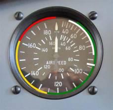
Air Speed Indicator |
|
|
|
|
|
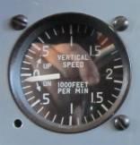
Vertical Speed Indicator |
|
|
|
|
|
Altimeter |
|
|
|
|
|
Magnetic Compass |
|
|
|
|
|
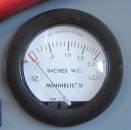
Differential Pressure Gauge |
|
|
|
|
|
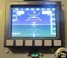
EFIS |
|
|
|
|
|
GPS In Docking Station |
|
|
|
|
|
Communications Radio |
|
|
|
|
|
Transponder |
|
|
|
|
|
Encoder |
|
|
|
|
|
Intercom |
|
|
|
|
|
Five Way Fuel Selector Valve |
|
|
|
|
|
Fuel Gauge |
|
|
|
|
|
Fuel Pressure Gauge |
|
|
|
|
|
Fuel Air Ratio Gauge |
|
|
|
|
|
Battery |
|
|
|
|
|
Engine |
|
|
|
|
|
Electric Fuel Pump |
|
|
|
|
|
Propeller |
10.5 |
|
|
|
|
Spinner |
|
|
|
|
|
Left
Main Fuel Tank |
|
|
|
|
|
Right
Main Fuel Tank |
|
|
|
|
|
Left
Auxiliary Fuel Tank |
|
|
|
|
|
Right
Auxiliary Fuel Tank |
|
|
|
|
|
Aileron
Trim Servo |
|
|
|
|
|
Elevator
Trim Servo |
|
|
|
|
|
Tail
Nav Light |
|
|
|
|
|
Right
Nav Light |
|
|
|
|
|
Left
Nav Light |
|
|
|
|
|
Landing
& Taxi Light |
|
|
|
|
|
Electro
Magnetic Compass |
|
|
|
|
|
ELT |
|
|
|
|
|
Nose
Wheel Pant |
|
|
|
|
|
Right
Main Wheel Pant |
|
|
|
|
|
Left
Main Wheel Pant |
|
|
|
|
|
Sound Proofing |
|
|
|
|
|
ITEM |
WEIGHT
Pounds |
ARM
Inches |
MOMENT
Inch Pounds |
|
Right
Main Wheel |
300 |
-16 |
-4800 |
|
Left Main
Wheel |
300 |
-16 |
-4800 |
|
Nose
Wheel |
150 |
10 |
1500 |
|
Computed
CG EMPTY |
750 |
-10.8 |
-8100 |
|
Calculating
Weight and Balance Prior to Flight |
|
|
|
|
Pilot |
180 |
-28 |
-5040 |
|
Passenger |
170 |
-28 |
-4760 |
|
Baggage |
25 |
-63 |
-1575 |
|
Fuel In L
& R Main Tanks |
144 |
-7 |
-1008 |
|
Fuel in L
& R Aux Tanks |
144 |
-7 |
-1008 |
|
Total
Carried Load |
663 |
|
|
|
Gross |
1413 |
-15.20948337 |
-21491 |
|
Takeoff |
|
|
0 |
|
LIMITS |
1420 |
-18 |
|
|
|
|
-10.8 |
|
|
|
Weight
Within Limits |
CG Within
Limits |
|
The weight
and balance table above shows the measured values in blue. Values that are fixed and do not change are
in black. The calculated values are in
red. The final results are shown with a
yellow background. The values shown are
for example only.
The values in the top part of the chart are based on measured weights and distances at the wheels. These values do not need to be recalculated unless there is a change in the equipment list above. The values on the bottom half of the chart need to be calculated for EACH FLIGHT.
Note: the
weight of fuel can be computed by multiplying 6.07 * Gallons.
(Note: There is a
spreadsheet “Weight&Balance.xls” that will calculate the values for
you. Use of the spreadsheet is the
preferred method as this will eliminate potential human error.)
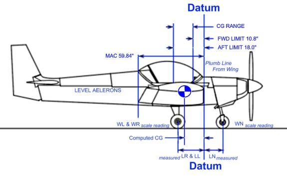
The lever
arm of the item is the distance to the data which is the front leading edge of
the wing.
Distances
forward toward the propeller are positive.
Distances toward the rudder are negative.
To compute
the Moments, multiply the weight of the item times the lever arm of the item.
Compute the
total moment by summing the moments of the items.
Compute the
total weight by summing the weights of the items.
Compute the
CG by dividing the total moment by the total weight.
Note: It would be
mathematically incorrect to sum the lever arms of the items to compute CG.
TBD THE ABOVE ARE FOR
PLANNING ONLY. THE REAL VALUES ARE TBD!
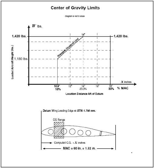
If the
gross weight is above 1,180 pounds plot your CG on the CG Limits chart below to
determine if you are in danger of overloading the nose wheel.
Airplane weighing procedure
A scale
capable of weighing loads of at least 400 pounds is required.
The
airplane should be empty of baggage, fuel and other materials.
Flaps
should up. Canopy and access panels should be closed.
The
airplane should be weighed in doors out of the wind.
The
airplane should be level fore and aft, port and starboard. Use blocks the thickness of the scale to
keep the plane level while it is being weighed. The longeron rail is level reference.
Record
the weight at each of the 3 wheels.
PERFORMANCE
Take Off Distances in Feet
|
Paved |
No Wind |
|
|
|
Altitude
Feet |
29° F |
59° F |
89° F |
|
0' |
450 |
490 |
550 |
|
3000' |
600 |
660 |
740 |
|
6000' |
800 |
880 |
970 |
|
Grass |
|
|
|
|
0' |
540 |
588 |
660 |
|
3000' |
720 |
792 |
888 |
|
6000' |
960 |
1056 |
1164 |
|
|
|
|
|
|
Paved |
10 Knot
Headwind |
|
|
|
Altitude
Feet |
29° F |
59° F |
89° F |
|
0' |
315 |
343 |
385 |
|
3000' |
420 |
462 |
518 |
|
6000' |
560 |
616 |
679 |
|
Grass |
|
|
|
|
0' |
378 |
411.6 |
462 |
|
3000' |
504 |
554.4 |
621.6 |
|
6000' |
672 |
739.2 |
814.8 |
|
|
|
|
|
|
Paved |
20 Knot
Headwind |
|
|
|
Altitude
Feet |
29° F |
59° F |
89° F |
|
0' |
247.5 |
269.5 |
302.5 |
|
3000' |
330 |
363 |
407 |
|
6000' |
440 |
484 |
533.5 |
|
Grass |
|
|
|
|
0' |
297 |
323.4 |
363 |
|
3000' |
396 |
435.6 |
488.4 |
|
6000' |
528 |
580.8 |
640.2 |
Above
distances decrease by approximately 25% for 10 kts of headwind and 40% for 20
kts of headwind.
Landing Roll
|
Paved |
No Wind |
|
|
|
Altitude
Feet |
29° F |
59° F |
89° F |
|
0' |
450 |
490 |
550 |
|
3000' |
510 |
560 |
620 |
|
6000' |
570 |
630 |
700 |
|
Grass |
|
|
|
|
0' |
360 |
392 |
440 |
|
3000' |
408 |
448 |
496 |
|
6000' |
456 |
504 |
560 |
Rate of Climb
(These will be adjusted after flight tests)
|
Altitude
Feet |
29° F |
59° F |
89° F |
|
0' |
744 |
720 |
656 |
|
3000' |
592 |
656 |
720 |
|
6000' |
640 |
720 |
792 |
Cruise Speeds and Range
|
Altitude
(Feet) |
RPM |
CAS - kts |
Range
miles |
|
S.L. 0 |
2500 |
103 |
820 |
|
3000' |
2600 |
108 |
880 |
|
6000' |
2700 |
112 |
900 |
|
9000' |
2800 |
116 |
980 |
These
speeds and ranges are based on a power setting of approximately 75% power. The endurance is about 10 hours depending on
various conditions, such as temperature, altitude and winds aloft and aircraft
loading.
Note:
reducing the power setting can reduce speed and fuel consumption and slightly
increase range.
Best Angle of Climb
TBD
Crosswind
The
demonstrated takeoff and landing crosswind component is 20 kts.
Service Ceiling
15,000
feet
Airspeed Calibration Table in Knots (Flaps Up)
|
KIAS |
35 |
50 |
70 |
90 |
110 |
120 |
|
KCAS |
|
|
|
|
|
|
Airspeed Calibration Table in Knots (Flaps Down)
|
KIAS |
30 |
40 |
50 |
60 |
70 |
80 |
|
KCAS |
|
|
|
|
|
|
The above
calibration shall be measured during the flight testing phase and recorded.
KCAS is
the corrected for instrument error in knots.
KIAS is
the indicated airspeed on the airspeed indicator in knots.
Stall
Speeds at 1400 pounds (Max take off weight)
Flaps up
Vs = _____ KIAS, 46 KCAS.
Flaps
Down Vso = _____ KIAS, 40 KCAS.
Emergency Procedures
The
following paragraphs provide an abbreviated checklist of what to do in different
emergency situations. The next section
will go into each of these in more detail and provide answers to why we follow
these steps.
Engine Fire During Start
Starter
continue cranking
If Engine Starts
Power 1700 momentarily
Engine Shut down and
inspect for damage
If Engine Fails to Start
Ignition OFF
Master Switch OFF
Mixture Full Lean
Fuel OFF
Pull Emergency Battery
OFF
Engine Failure During Takeoff
Throttle IDLE
Brakes APPLY
Flaps UP
Mixture Full Lean
Ignition OFF
Pull Emergency Battery OFF
Engine Failure After Takeoff
Airspeed 60
Mixture FULL LEAN
Fuel Selector OFF
Ignition OFF
Flaps AS REQUIRED
Pull Emergency Battery OFF
Engine Failure In Flight (Restart Procedure)
Airspeed 60
Fuel Selector MOST FULL
Aux Fuel Pump ON
Mixture RICH
Ignition Select OTHER
Carb Heat ON
Check Gauges for cause of power loss
Power Off Landing (assumes off runway)
Airspeed 45->50
Ignition OFF
Pull Emergency Battery OFF
Fuel Selector OFF
Mixture FULL LEAN
Check Seat Belts are secure
Canopy Opening in Flight
Keep your hands on the controls
Lower airspeed to 60
FLY the aircraft
Land as soon as practical
WARNING: Do not try to close the
canopy in flight! Fly the Aircraft.
Precautionary Off Runway Landing
Check that seat belts are secure
Fly as needed to make the field.
Right Before touch down, Emergency Battery OFF
Low Speed, Nose High is best at
touch down.
Brakes WITH CAUTION
Fire In Flight
Look for source of the fire
Electrical Fire (Smoke in cabin):
Master Switch ………….OFF
Vents…………………… OPEN
Cabin Heat ……………. OFF
Fire Extinguisher………. AS NEEDED
Land as soon as
practical.
Engine Fire:
Cabin Heat……………. OFF
Fuel Selector.…………. OFF
Throttle………………… CLOSED
Mixture………………… FULL LEAN
Aux Fuel Pump………. OFF
Proceed with Power Off
Landing
Loss of Oil Pressure
Reduce Power
Prepare for Off Field Landing and
land as soon as practical.
Loss of Fuel Pressure
Aux
Fuel Pump………………… ON
Fuel Selector…………………… Select Most Full
Land at nearest airport and
investigate problem.
High Oil Temperature
Reduce power setting
Land at nearest airport and
investigate problem.
Alternator Failure
Reduce
Electrical Load as much as possible
Cycle Power on Alternator
Land
as soon as possible and investigate
Spin Recovery
Rudder………………………… Full Opposite Direction of Spin
Ailerons……………………….. Full Opposite to Spin Direction
Pitch…………………………… Full Forward
When rotation stops, rudder neutral
and ease controls back to recover from dive.
Engine Roughness
Carb Heat……………………. ON
Mixture……………………….. Adjust for max smoothness
Fuel Selector………………… Switch to most full
Engine Gauges……………… Check
Ignition Select……………….. Change to Other
Prepare for power off landing,
continue to nearest airport.
ICING
Carb Heat……………… ON (adjust for best power)
Turn Back and or change altitude to
obtain outside air less conducive to icing.
Cabin Heat……………. FULL ON
Full Power…………….. Higher Engine
speed reduces icing on propeller.
Plan to land at the nearest airport.
Be prepared for significantly higher
Stall Speed.
Electrical Power System Malfunctions
Volt Meter shows excessive voltage
Alternator………………………………. OFF
Non Essential Electrical
Equipment…. OFF
Land as soon as
practical.
Volt Meter shows low voltage
Radios…………………………………… OFF
Alternator
Fuse…………………………. CHECK
Non Essential Electrical
Equipment…. OFF
Radios…………………………………… ON
Land as soon as
practical
Electric Trim Failure
In the case of electric trim failure the pilot may no longer
be able to neutralize pitch or roll control forces. These may become very heavy.
Adjust speed and power to minimize these forces and be prepared for
extremely high forces required on controls especially during landing.
Lightning Strike
Land as soon as practical to check for damage.
Amplified Emergency Procedures
The
previous section gave emergency procedures in a simple checklist form. In this section we will look at these
emergency situations in more detail..
Engine Fire During Start
Engine Fires during start are often caused by over priming
or flooding the carburetor with gas while attempting to start the engine. In this case the first attempt to extinguish
the fire is get the engine started.
This will consume the excess fuel and help blow the fire out.
If the engine fire doesn’t stop immediately after starting
the engine then the engine should be shut down (Mixture Full Lean) and the fire
put out with the best means available.
Engine Failure During Takeoff
The proper action in an engine out during takeoff depends
largely on the particular circumstances.
If sufficient runway remains to
complete a normal landing, land straight ahead.
Any turn at low speed will increase the risk of a stall
spin, fatal at low altitude. Maintain a
safe airspeed and keep turns at a minimum landing as straight ahead as
possible.
If sufficient altitude has been gained to attempt a restart,
maintain a safe airspeed, check the fuel selector, turn the aux fuel pump ON,
set mixture RICH, and carb heat ON.
If power is not regained proceed with power off landing.
Engine Failure In Flight (Restart Procedure)
First.
Fly the airplane. Set 60 knots for best
glide. Prepare for an emergency
landing.
The most common cause for engine power loss is fuel
starvation. In those cases the engine
power will return soon after fuel supply is restored. This can take about 10 seconds for the empty fuel lines to be
filled once the fuel is flowing.
Turn the auxiliary pump ON, and change the fuel selector
valve to a different tank with fuel in it.
A different tank because sometimes fuel gauges cannot be trusted.
Check the mixture is RICH.
Fuel can be starved by inadvertently leaning the mixture to the fuel
starvation point.
Another common cause of power loss is carburetor ice. Turn the carburetor heat ON.
Change the ignition selector from one coil to another in
case the problem is an ignition problem.
If power is not restored proceed
with an emergency landing.
Power Off Landing
If
a loss of power occurs at altitude, trim the airplane for best glide (about 60
knots) and look for a suitable field.
If altitude is sufficient check the GPS for the nearest airfield. If altitude is sufficient to land safely at
the nearest airport aim for that airfield.
Otherwise pick the best alternative landing sight visible.
If
possible, notify Air Traffic Control of your situation, your location and
intentions.
When
committed to a landing use flaps as needed.
If
landing off field:
The fuel
selector should be OFF and Emergency Battery Cutoff should be pulled to the OFF
position. These steps are to reduce the
risk of fire in an off field landing.
Seat
belts should be tightened.
Land at
the lowest possible speed, keeping in mind the stall speed of 45 knots.
Use
brakes with caution to avoid flipping the airplane on rough or soft terrain.
When the
airplane comes to stop exit the airplane.
Canopy Opening in Flight
The main thing to remember if this
happens is to FLY THE AIRPLANE. A
canopy can come open during flight if not properly latched. There would be a LOT of wind noise in such
an event. Anything lying loose in the
cabin will be sucked out.
If the
canopy should open in flight, lower the airspeed to 60 KCAS, and land as soon
as practical.
If the
flaps are down bring them back up and prepare for a flaps up landing.
DO NOT
TRY TO CLOSE THE CANOPY. The canopy
will be OK if you land the airplane. The force required to close a canopy in
flight is beyond the strength of most people and will only take the pilots mind
off the most important thing, which is to fly the airplane. Especially do NOT remove your seat belts to
reach the canopy. You could be pulled
out of the aircraft.
Fire In Flight
Look for
source of the fire. If the fire is
coming from in the cabin open both fresh air vents to reduce the smoke. Turn the master switch off to remove the
probable electrical source of ignition.
Use a
fire extinguisher to put out the fire.
Land as soon as possible.
If the
fire is in the engine compartment, turn the fuel selector to OFF and close the
throttle. The mixture should be pulled
FULL Lean. Make sure the auxiliary fuel
pump is OFF. Push Cabin Heat OFF to
keep smoke and fire out of the cabin.
Turn the Master switch OFF. Fire
in the engine compartment can be spread as wires loose insulation and begin to
short. Proceed with a power off
landing.
Loss of Oil Pressure
Partial Loss of oil pressure usually
indicates a malfunction in the oil pressure regulating system. Land as soon as possible to prevent engine
damage.
If the pressure gauge indicates a
complete loss of oil pressure it could mean either a low oil level or a faulty
oil pressure sensor or gauge. In either
case proceed to the nearest airport at a reduced power setting and be prepared
for engine failure and a forced landing.
Loss of Fuel Pressure
Loss of fuel pressure can be caused
by a number of failures. This could be
due to fuel exhaustion, failure of the fuel pump or a clogged fuel line. The airplane has a main mechanical pump and
an electric auxiliary pump. Switch the
auxiliary pump on. If fuel pressure
does not return switch to a different fuel tank even if the fuel level gauge
indicates that the tank is full. It is
necessary when switching the fuel selector valve to also switch the tank sensor
selector switch.
Land as
soon a possible to have the fuel system checked to identify the problem. Be prepared to make an emergency power off
landing.
High Oil Temperature
Abnormally high oil temperature may
indicate either a low oil level, or a blockage of the cool air intake
baffles. Land as soon as possible to
resolve the issue. Watch for a loss of
oil pressure. A complete loss of oil
pressure is usually followed by engine failure. Be prepared to make an emergency power off landing.
Alternator Failure
A drop in
voltage can indicate an alternator failure.
If the voltage is 12 volts or less then less current is being provided
than is being consumed. Check for a blown alternator fuse. Reduce the electrical load as much as
possible. Switching the Master switch
off removes all electrical loads other than the ignition system. Switch the alternator off and back on. Land at the nearest airport to investigate
the issue.
Spin Recovery
Intentional
Spins are prohibited. In case of an
unintentional spin apply full opposite rudder to the direction of the
spin. Push the nose down sharply to
gain airspeed. Apply ailerons fully in
the opposite direction of the spin. If
flaps were down, bring them back up.
When rotation stops center the rudder in the neutral position and ease
controls back to recover from dive.
Stalls
Power off
and Power on stalls in this aircraft have similar behaviors. There is no sudden brake, but a gradually
“mushing” as the plane begins to sink.
Recovery is quick when the nose is lowered, usually requiring less than
150 feet of altitude loss.
Engine Roughness
Engine
roughness can be caused by carburetor icing, too lean of fuel air mixture or
running too long with a very rich fuel air mixture. It can also be caused by a failure of an ignition component such
as coil or ignition points. Any of
these cause will usually be accompanied by a loss of engine RPM and power.
In the
case of carb ice, apply carb heat and full power. The engine should soon return to smooth operation.
Check the
fuel air mixture gauge. The optimum
reading is 14:1. If the reading is
higher push the mixture toward rich. If
the reading is lower, pull the mixture toward lean.
If the
cause was a rich fuel mixture it may take some time to recover as this is an
indication of spark plug fowling.
If the
cause was a lean mixture it should return to smooth running quickly when the
mixture is enriched. However running
too lean for any period of time can cause permanent engine damage.
If the
cause is ignition component failure switch the ignition selector from one
ignition to the other. This should
provide immediate resumption of smooth running.
In any
case prepare for a power off landing and return to the nearest airport.
Normal Procedures
Pilots
should become familiar with this section for the safe operation of this
airplane.
Airspeeds for safe operation
|
|
|
KCAS |
KIAS |
|
Vy |
Best Rate
of Climb (flaps up) |
60 |
TBD |
|
Vx |
Best
Angle of Climb (flaps up) |
58 |
TBD |
|
Vc |
Turbulent
Air Operating Speed |
108 |
TBD |
|
|
Landing
Final Speed (flaps down) |
55 |
TBD |
|
Vfe |
Max Flaps
Down |
70 |
TBD |
|
Vne |
Never
Exceed Speed |
140 |
TBD |
|
Vs |
Stall
Speed at Max weight (flaps up) |
43 |
TBD |
|
Vso |
Stall
Speed at Max weight (flaps down) |
38 |
TBD |
|
Va |
Maneuvering
Speed |
82 |
TBD |
|
Vc |
Cruising
Speed |
108 |
TBD |
General Operations
Crosswind
Limitation: 20 Knots
Service
Ceiling: 15,000 feet
Load
Factors Limits
Flaps Up: Positive
+ 4 G, Negative –2 G
Flaps Down: Positive + 2 G, Negative 0 G.
Prohibited
Maneuvers:
Intentional Spins are prohibited.
Aerobatics are prohibited.
Types of
Operation:
This
airplane is approved for the following operations when equipment is in working
order:
Day VFR
Night VFR.
Flight
into known or forecast icing conditions is prohibited.
(Consider
moving weight and balance section to here)
Walk Around
1.
Open
Canopy
2.
Check
Cockpit:
a.
Ignition
key OFF
b.
Master
Switch ON
c.
Throttle
Pull Idle
d.
Fuel
Selector ON
e.
Fuel
Gauges Select Tanks and check quantity
f.
Flaps Down
g.
Master
Switch OFF
3.
Front
Left Wing:
a.
Check
left side of canopy for condition
b.
Drain Fuel
Samples from both left tanks and gascolator checking for containments like
water
c.
Inspect
Left Main Landing Gear and tire for condition.
d.
Look
for leaking brake oil.
e.
Check
Pito
f.
Confirm
Fuel Level visually
g.
Secure
Gas Caps
4.
Left
Wing Tip
a.
Remove
Wing Tie Down
b.
Check
Wing Tip for damage.
c.
Check
Wing Surfaces for damage.
d.
Check
Lights for damage.
5.
Left
Wing Rear:
a.
Check
Aileron condition
b.
Check
Aileron for Freedom of movement.
c.
Check
Left Flap hinge for safety.
d.
Check
Left Flap condition.
e.
Raise
Flaps and check travel.
6.
Fuselage
Left Side:
a.
Check
Left Side of fuselage for damage.
b.
Check
Antennas.
7.
Empennage
a.
Check
Elevator and Rudder condition.
b.
Check
Elevator freedom of movement.
c.
Check
Cables cotter pins and tension.
d.
Check
Elevator hinge safety.
e.
Check Electric Trim Tab Condition
f.
Remove
Tail Tie Down
g.
Check
condition of rudder navigation light.
8.
Right
Fuselage and Rear Right Wing:
a.
Check
access cover secure
b.
Fuselage
condition.
c.
Check
right flap for safety.
d.
Check
right flap condition.
e.
Check
aileron freedom of movement.
9.
Right
Wing Tip:
a.
Check
Right Wing surface for damage.
b.
Check
Wing Tip for damage.
c.
Check
Nav Lights for condtion.
d.
Remove
Right Wing Tie Down.
e.
Check
Angle of Attack Probe.
10. Front Right Wing:
a.
Check
Fuel Level Visually
b.
Sample
Fuel from both tanks for contaminents at the drain.
c.
Check
Right Side of Canopy for Condition.
d.
Inspect
Right Main Landing Gear for condition.
e.
Check
the Tire for air level and general condition.
f.
Look
for leaking brake fluid.
11. Right Side Cowl Rear
a.
Check
Cowling for damage, condition of fasteners.
b.
Check
cabin cool air inlet for blockage.
c.
Open
Dipstick Door and check oil level.
d.
Close
Dipstick Door securely.
e.
Open
Oil Cap Door and check that oil cap is secure.
f.
Check
Noise Gear Bungy.
g.
Check
for buckled mettle around the bungy from hard landings.
h.
Secure
Oil Cap Door completely.
i.
Check
that muffler is not loose.
12. Right Side Cowl Forward
a.
Check
for loose or missing fasteners
b.
Check
for carburetor air blockages.
13. Cowl Front Right Side:
a.
Remove
Tow Bar if present
b.
Check
Nose Gear and Wheel Pant for condition
c.
Check
Tire for Condition and air pressure.
d.
Check
Propeller for condition.
e.
Check
Coil Air Intakes for blockages.
f.
Check
Spinner for condition
14. Cowl Front Left Side:
a.
Check
Air Intake for blockages.
b.
Check
Propeller and Spinner for condition.
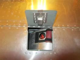
c.
Open
Battery Access cover.
d.
Check
that alternator is secure.
e.
Check
that belts are tight and not overly worn.
f.
Look
for buckled mettle from hard landings.
g.
Close
access cover securely.
h.
Look
for loose or missing fasteners.
i.
Check
cabin cool air inlet for blockages.
Inside Airplane Pre-Flight Inspection
1.
Control
Stick should have free smooth operation, no binding or contact with the cabin
seat or instrument panel. There should
be no free play (slack) in the controls, nor should the controls be hard to
move.
2.
Rudder
Pedals should move through the full range of motion smoothly without
binding. Shoes should not catch on
anything around the peddles.
3.
Toe
Brakes should be firm with no tendency to bleed down or lock up. Inspect brake master cylinder area for
leaks. There must be no leaks.
4.
The
instruments should secure and placards in place.
5.
Engine
Controls should be inspected and operate smoothly. Check the friction lock on the throttle for proper
operation. Check the push and release
mechanism on the mixture control for proper operation.
6.
Safety
belts must be in good condition and working order.
7.
Avionics
and electrical checks. Check that the
radios are transmitting and receiving on the desired frequencies. Check the headset and microphone for
operation. Inspect the circuit breakers.
With the master switch on “If it glows, it blows”. Glowing circuit breakers are blown. Test the ELT for operation. Check Lights and GPS. Other instruments can
be checked during the run up.
8.
Check
the canopy latch. Push down hard on the
rail above the latch. You should hear a
‘click’ when the latch is engaged.
9.
The
weight and balance for the aircraft should be carefully done. Determine CG and gross weight are in the
safe range prior to flight.
10. This Pilot Operating Handbook,
weight and balance computation, Operation Limitations, Registration and
Airworthiness Certificate must be on board.
11. All controls and instruments must be
labeled and the Experimental Placard must be readable.
12. The weather must be good enough for
VFR conditions.
13. Windshield should be clean and
clear.
Minimum Equipment
The
following equipment is necessary for DAY VFR flying. If any equipment on this
list is not operational it should be placarded and the airplane should not be
flown.
Remember TOMATO FAMES:
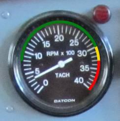
Tachometer
Oil Pressure
Mixture Gauge
Altimeter
Temperature
(CHT)
Oil Temperature
Fuel Gauge
Air Speed Indicator
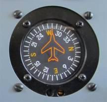
Magnetic Compass
ELT
Seat Belts
|
|
DAY VFR |
NIGHT VFR |
|
Flight
Instruments |
airspeed
indicator |
magnetic
compass or EFIS |
|
|
altimeter |
|
|
|
compass |
|
|
Engine
Instruments |
Fuel
Level |
Volt
meter |
|
|
Oil
Pressure |
|
|
|
CHT |
|
|
|
Tachometer |
|
|
Lighting |
|
Position
Lights |
|
|
|
Strobe
Lights (anti collision) |
|
|
|
Landing
Light |
|
|
|
Taxi
Light |
|
|
|
Instrument
Lights |
|
|
|
cabin
light (may use flashlight) |
Night VFR
requires these additional pieces of equipment.
Remember FLAPS.
Fuses (spares)
Landing Light
Anti-Collision Lights (on each wing and the rudder)
Position (strobe lights, on each wing)
Source of Electricity (alternator)
To this
we also add
Taxi Light
Panel Lights
Cabin Reading Light (Between the
seat backs, or a flash light)
Placards
Any equipment found not to be operational should be
placarded. The placard should state in
an easy to see warning “<Item Name> Not Functional!” If the item is part of the minimum equipment
for Night Flight a placard should be attached that states “Night Flight
Forbidden”. If any equipment on the day
VFR minimum equipment list is not functional, a placard should be installed
that reads “Flight Forbidden, Aircraft Not Flightworthy” and a placard on the
necessary equipment should be made and piece of tape should be placed over the
ignition switch as a reminder.
Other Considerations
You must
be able to answer the following questions with NO before flying the aircraft.
Has the
aircraft been inspected for structural damage since fly windy or turbulent air
above Va speed?
WARNING: Do not fly the aircraft after flight above Va into
turbulent air without a thorough structural inspection of the wing root area.
Has the
aircraft been tied down outside without control locks?
WARNING: Damage to the controls can
result from being tied down outside on a windy day.
Are there
any notifications or service bulletins from the designer that have not been
complied with?
WARNING: Make sure you are up to
date with service bulletins from the manufacturer.
Are the
control cables loose or overly tight?
WARNING: Do not fly the aircraft
with loose, sloppy or damaged controls.
Is there
a gap between the flap stop while in the up position?
Has the
flap been stepped on?
WARNING: Damage to the flaps can occur if they are stepped
on. A damaged flap can make the
aircraft unsafe to fly.
Are the
colored arcs on the ASI incorrect or missing?
WARNING: No the aircraft limitations
before flying
Does the
canopy not latch securely on both sides?
WARNING: Do not fly the aircraft is
the canopy latch is not functioning properly.
WARNING: Do NOT try to close the
canopy in flight. Fly the aircraft!
Before
Starting the Engine:
Check the controls again. Check brakes and seat belts. Check that canopy is closed securely.
General Operation
Fuel
should be 93 Octane (alcohol free) Auto gas or 100 LL aviation fuel. 100 LL is preferred.
Starting
1.
Fuel
Selector to an appropriate tank.
2.
Fuel
Gauge Selector the selected tank.
3.
Ignition
Selector switch to the right (TBD, this might change)
4.
Mixture,
Rich
5.
Throttle
Full Open
6.
Electric
Fuel Pump ON
7.
Start
by turning ignition switch to the start position and release once started.
8.
Adjust
throttle immediately to idle.
9.
Oil
Pressure Check. (If no pressure in 30 seconds shut down the engine)
If flooding is suspected
1.
Throttle
Full OPEN
2.
Mixture
Full Lean
3.
Start
by turning ignition switch to start position then release when started.
4.
Throttle
back to 1200 RPM.
5.
Mixture
Rich.
6.
Oil
Pressure Check. (If no pressure in 30 seconds shut down the engine)
Taxiing
1.
Check
wind conditions and add extra caution in windy conditions while taxiing.
2.
Set
and check radios and GPS.
3.
Check
Flaps Up.
4.
Set
trim to neutral.
5.
Check
fuel selector on desired tank.
6.
Check
fuel level in all tanks then back to selected tank.
7.
Select
Lights as required, and check.
8.
Check
mixture in Rich 14+ range.
9.
Check
Auxiliary fuel pump On.
Ground Run Up
1.
Warm
up at 900 to 1200 RPM.
2.
Adjust
Mixture to 12:1 ratio.
3.
Minimum
oil temperature is 75 degrees F.
4.
Increase
engine speed to 1700 RPM long enough to perform the following checks.
a.
Switch
ignition selector from right to left. Wait a few seconds then switch it
back. The engine should operate
normally on both ignitions, but the tachometer will operate when the right
ignition is selected.
b.
Pull
carburetor heat on. A slight drop in
engine RPM should be noted.
c.
Return
engine to idle.
5.
Instrument
Check
a.
Oil
Pressure should not be low or fluctuating.
b.
Oil
Temperature should be in the (low – high) range.
c.
CHT
should be in the (low – high) range.
d.
Voltage
should be above 13 volts.
e.
Mixture
should indicate Rich (around 12:1 ratio)
f.
Fuel
Pressure should indicate (3-5psi) guess.. correct later
g.
Altimeter
should indicate field altitude.
6.
Fasten
Seat Belts securely
7.
Check
Canopy is latched securely
8.
Check
freedom of movement of control surfaces.
Normal Takeoff
1.
Release
Brakes
2.
Lineup
with runway.
3.
Slowly
advance throttle to full
4.
Rotate
at approximately Vy, 60 knots.
Climb
1.
Best
angle of climb over obstacles is 58 KCAS (?)KIAS.
2.
Best
rate of climb is 60 KCAS (?) KIAS.
3.
Throttle
Max Power output is 2900 RPM.
4.
Trim
the aircraft to relieve stick pressure.
5.
Check
Oil temperature and pressure is within limits.
6.
Check
CHT remains in limits.
7.
IF oil
temperature or CHT go above limits reduce the rate of climb and increase speed.
Cruise
1.
Aux
pump off.
2.
Throttle
power to 75% (about 2400 RPM) (This should result in 110 to 120 knots)
3.
Trim
for level flight (hands off)
4.
Set
mixture to peek 14:1 ratio.
5.
Maintain
fuel tank balance between left and right tanks. Swap tanks at 15 minute intervals.
6.
When
swapping tanks at the selector valve switch to the corresponding fuel level
sensor.
7.
Check
oil and CHT temperatures at regular intervals.
8.
Check
oil pressure at regular intervals.
9.
Check
electrical system is maintain charge of around 12 volts.
10. If any warning light comes on divert
to the nearest airport.
11. If rough air is encountered reduce
speed to 82 knots.
12. If a speed is seen increasing check
for an unintended decent.
13. If speed is seen decreasing check
for unintended climb.
Decent
1.
Add
carb heat.
2.
During
decent it may be necessary to adjust the mixture to more rich. Look at
maintaining 14:1 ratio.
3.
Adjust
trim for controlled decent.
4.
Decrease
power setting to around 1000 RPM to maintain 60 to 65 knots.
Approach to Landing
1.
Get
radio clearance from tower or warn traffic of approach.
2.
As you
approach for landing add flaps beginning at 75 knots.
3.
Do not
allow air speed to drop below 50 knots.
4.
Push
the stick into the wind to counter cross wind.
5.
Use
rudder to keep the aircraft aligned with the runway.
6.
If
anything is bad (off center, too slow, too fast) then apply full power, and
remove flaps for a go-around.
Landing
1.
Aim
for a touch down speed of 50 to 55 knots.
2.
As you
approach the runway reduce power to idle and bring the nose up slightly to
bleed off extra speed.
3.
Let
the plane settle onto the runway.
4.
At
touch down add backpressure to prevent pitching forward.
5.
At
touch down the nose gear will begin steering. Be prepared for a change in
direction due to opposite rudder.
6.
Apply
breaks carefully.
7.
After landing
flaps up.
Taxiing Back
1.
Remove
carb heat. Carb heat is unfiltered and
it is not recommended for ground operations.
2.
Apply
necessary controls for crosswind controls.
Keep stick into the wind while wind is coming from front. Keep stick with the wind if from back.
Shut Down
3.
Lights
OFF
4.
Mixture
full lean Full Out.
5.
Throttle
to Idle Full Out.
6.
Aux
pump OFF.
7.
Avionics
OFF.
8.
Lights
OFF.
9.
Ignition
OFF.
10. Main Power OFF.
Tie Down
When the
aircraft is not in use it should be anchored to the ground with appropriate tie
downs and the wheels blocked.
Controls
locks should be placed on the controls to prevent wind damage.
If the
aircraft is to be parked for a prolonged period outside the follow precautions
should be taken.
Covers
should be put on pito, AOA probe and covers over engine inlets to prevent birds
or bugs from clogging the cooling fins.
Covers
should also be put over the fuel vents on the bottoms of the wings.
Covers
should be put over the carb inlet to prevent birds from clogging carb inlet.
Covers
should be brightly colored and have flags visible from a casual walk around.
Night VFR Operation
The
aircraft is outfitted for night VFR operation.
Minimum Equipment
Night VFR
requires these additional pieces of equipment.
Landing Light
Taxi Light
Navigation Lights (on each wing and
rudder)
Strobe Lights (on each wing)
Panel Lights
Cabin Reading Light (Between the
seat backs)

After
engine start, panel lights, taxi lights, landing lights, navigation lights and
strobe (anti collision) lights should be turned on.
After
reaching cruise altitude and exiting the airspace around the airport the
landing light and taxi lights can be turned off.