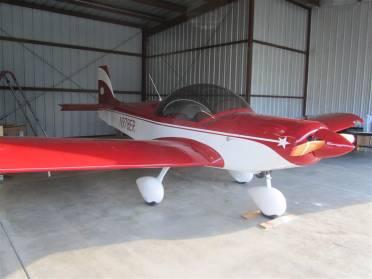
This manual is for maintenance of the scratch built Zenith
Zodiac CH601XL aircraft built by Daniel Dempsey between May 2004 and July
2013.A maintenance log will accompany
this manual.Each scheduled inspection
will include a log entry describing the inspection being conducted.The log entry will include the date,
operating hours, and details of issues addressed and any costs incurred.Part numbers, vendors and costs will be
logged for any parts or materials used.All maintenance performed on the aircraft will be entered in the log
whether or not they occur at the scheduled inspection periods.
Any changes made to the equipment or airframe should be
noted in the log and a new weight and balance should be performed.
Flight controls are an important part of all inspections
from the pre-flight to the annual condition inspection.The following signs of ware should be
watched for and corrected when found.
Cables
should be properly tensioned
Cables
should not look worn of frayed
Cable
wire ties should be in place
Control
movement should be free of binding or obstruction
Bolt
witness marks should indicate the nuts have not moved on bolts
Hinges
pins should in their proper place
Control
surfaces should be free of cracks or other damage
Minor
Dents and Skin imperfections are permissible
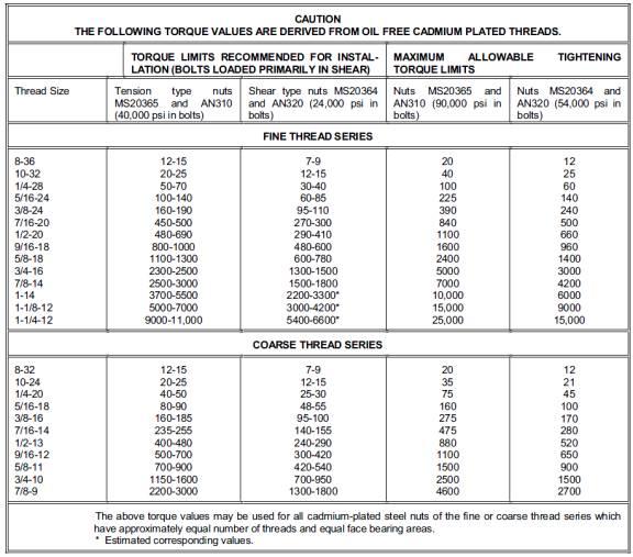
Only correct aircraft quality AN hardware should be
used.Self locking ny-lock type nuts
should be used only on clamping joints, not where parts move against each
other.If the bolt is used for a pin
where a part moves against it, the nut should be castle nut with cotter
pin.Bolts should be the proper length
per (give reference here)
Initial trim adjustments should be made according to the aircraft
designers following the diagrams in the drawings.
Further adjustments can be made after test flights to
confirm the aircraft flies hands off.
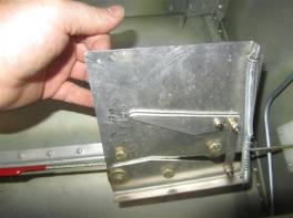
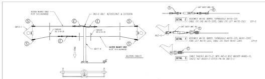
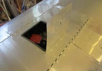
Aileron neutral position is adjusted inside the aileron bell
crank access panel.
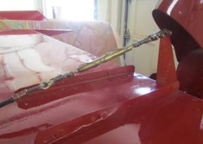
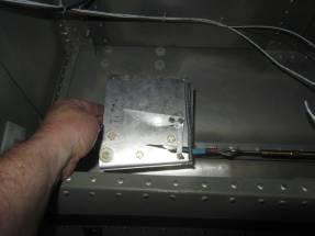
The rudder neutral position is adjusted by loosening one
rudder cable and tightening the other.When setting the rudder cable tension it is necessary to jack the front
of the airplane up to take the weight off of the front nose wheel.Failure to do this will cause the cable to
become over tight when you leave the ground.A good jacking point is behind the nose gear mounting point.A 2x4 block of wood laid in the channel can
be used to spread the load.
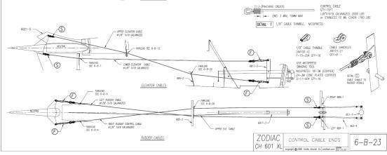
The elevator neutral position is adjusted by loosening or
tightening the top cable and inversely tightening or loosening the other
cable.The top cable adjustment is
under the rudder saddle.The bottom
adjuster is under the arm rest.
Aileron trim neutral position is adjusted inside the aileron
trim access cover on the bottom of each wing.
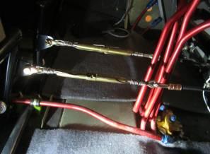
The dual stick center position can be adjusted at the stick
connecting rod attachments in front of the seats.
Pitch and roll trim can be made in flight using the trim
controls, but initial adjustments should be made to put the electric trim in
the middle of it’s range while controls are in the neutral position.
The flaps neutral position is adjusted by adjusting the
length of push pull rod under the arm rest.The flaps relative positions are not adjustable without making a new
flap lever bearing at the flap.This is
made from 1/8” nylon, the bearing whole is ¼” and the bearing is held in place
by 5/32 avex rivets.
Trim is also adjusted in flight with aileron and elevator
trim tabs controlled by Ray Allen servos bought from Aircraft Spruce, Part No.
11-11505 T2-7A. These servos came with the control buttons and indicators also
from Ray Allen. Maintenance covers on the left aileron and
the left elevator provide access to the servos.
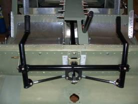
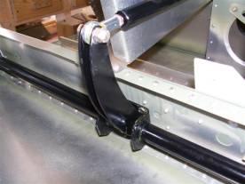
If nose gear of the aircraft has a bungy cord type
suspension.The bungy should replaced
if it shows any signs of wear or the cord is more than 5 years old.
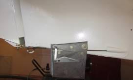
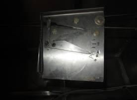
The drawing to the left shows a method for stretching or
relaxing the bungy cord for replacement.A piece of threaded rod and nut is used to stretch the bungy.
Blocks of wood form the rest of the fixture. Remove the top
stop plate on the tubing by removing 2 screws.Release the tension by backing off the nut on the threaded
rod.Remove the bolts hold the bottom
bearing block.The top of the tube will
drop through the top green plastic bearing block.Once it is low enough to release all the tension on the bungy,
pull the cotter pin from the rod that holds the bungy to the firewall
structure.Pull the rod will release
the bungy.Slip the bungy over the top
of the gear tubing and replace with the new one.Reverse the process to reassemble the gear.
The toe brakes must be checked regularly for fluid level and
wear.
The brake master cylinders are located behind each rudder
peddle.The cover is held on by a snap
ring and snap ring pliers are necessary for removing them.The proper fluid to use is 5056 (Airoshell 41).This can be purchased from Aircraft Spruce.A spungy feel to the brakes is an indication
that air has been trapped in the lines.If this occurs have the brakes bled before flying.Check for drips of fluid on the tires and
around the main tires on the pavement.
Brake function can be verified in the following way.While taxiing the aircraft equal brake
pressure should cause the airplane to stop straight.Both brakes should feel hard when pressure is applied.Spunginess indicates air in the brake lines.
Bleeding the brakes is best done with 2 people.First remove the wheel pants from the main
gear.Remove the cover on the master
cylinder being bled with a snap ring pliers.Fill the resevoir with 5056 brake fluid.Pump the brake until it feels firm.Keep pressure on the brake while the other person unscrews the
brake bleed screw on the wheel caliper.Close the bleed screw.Communicate that the bleed screw is closed before the person pumps the
brakes again.Repeat the process until
the spunginess is removed.Replace the
master cylinder cover.
The brake pads on new brakes are about ¼ inch thick.If the pads become less than 1/8th
of an inch thick in any place they should be replaced.To check the brake pads remove the main
wheel pants.
To replace the pads, remove the wheel by removing the cotter
pin on the wheel hub.Remove the nut
holding the wheel on.Remove both 3/16
bolts holding the sides of the caliper together.These are on the backside of the brake calipers.Remove the wheel and roller bearing from the
hub.Both brake pads can be slid off of
the guides.
Brake disks should show no signs of gouging.If they have gouges from worn out pads
rubbing them they should be removed and turned on a lathe to remove the
gouges.If the disks are less than
3/16” thick in any place they should be replaced.
Describe regularity of oil changes and type of oil used
Castrol Syntec 20w-50.
Maintain an in flight awareness of the health of the oil
system.The oil temperature should
remain below 450 degrees in cruise flight, and above 300 degrees. The absolute
high CHT is 575 degrees and only for brief periods.The oil pressure should remain above 30 and below 50 psi.
Maintain a log of oil usage as part of the flight logs.Excessive usage is reason to have the engine
overhauled.One quart per 8 hours of
flying time is the limit.
The oil drain plug is accessed by removing the air intake
scoop on the bottom of the cowling.Remove 6 phillips head screws to remove the scoop.The oil drain is directly above the front of
the scoop.Remove the oil drain plug
with a ¾” wrench.Use a fine screen in
your oil funnel while draining to inspect for metal shavings in the sump.The oil should have a honey color and consistency.If it is dark brown and thin it may have
been over heated.
To remove the oil filter lift the pilot side cowling cover
by first withdrawing the quarter turn fasteners (camlocks).The oil filter is on the back of the engine
next to the alternator.Remove the
filter by loosening the 9/16 (?) bolt above the filter.Replace with a new filter and bolt gasket.
Cut open the filter and inspect for metal particles.
Use a new copper gasket on the drain plug.
Use only high quality synthetic motor oil like Castrol
Syntec 20w-50.
The oil filler can be accessed by opening the oil fill quick
access cover in the top center cowling.
When changing the oil it’s a good time to inspect and change
the air filter.The air filter can be
accessed by removing the 6 phillips head screws holding the air filter housing
cover in place.Check that the SCAT
duct is clear of debris and isn’t cracked or punctured.There should be dirt on the outside of the
filter but not inside.Look for and
resolve signs of air leakage past the filter.The hose clamp at the filter inlet should be in place and in good
condition. Look at the carburetor heater SCAT duct to the heat muff for signs
of cracks or holes.Note that
carburetor heat is NON FILTERED!Use of
carburetor heat while on the ground is not recommended.Check the carburetor heat inlet for signs of
blockage from birds or insects or other material.Replace with a new FRAM CA3915
The fuel system is fed by 4 fuel tanks in the wings.All fuel lines are aluminum except for those
going from the firewall to the engine.These are rubber with a stainless mess sleeve.
Each fuel tank has a quick drain at the lowest point.These should be used to check the fuel for
water before each flight.
Fuel lines run from each tank to a 5 way selector valve from
Andair.
Gascolator
From there the active tank line is fed to a gascolator at
the lowest point on the system.
This also has a
quick drain to be check before each flight.From the gascolator the fuel is fed to bulkhead fitting at the firewall.
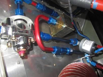
Firewall forward the fuel enters a tee and is fed to the
main mechanical pump on the engine, and to an electric backup pump on the
firewall.
After the pumps each fuel line has a check valve to prevent
fuel from one pump from forcing fuel back toward the tank through the other
pump.After these check valves the
lines come back together at a tee.
After the final tee, the fuel flows though a fuel pressure
regulator then to a pressure sensor connected to a fuel pressure gauge on the
center console.The fuel line
terminates at another bulkhead fitting where a flexible fuel line takes the
fuel the final step to a custom made banjo fitting on the SU carburetor.
Tires are to be changed when the tread is worn off or the
sidewalls of the ties are cracking due to dry rot.
The wheels on the aircraft can be split down the center. Remove the wheel from the aircraft by
removing the cotter pin that holds the hub nut in place, then remove the hub
nut.Be careful not to get dirt in the
wheel roller bearings. The wheels can be split by First remove all the air from
the tire by pressing on the valve center in the valve stem.To split the wheel remove the 4 bolts that
hold the halves together.
The tires should be replaced if the tread is worn
completely off in any spot.
The fuses
are of type (If it glows the blow), which means they glow when they are
blown.This makes identifying a blown
fuse trivial.These fuses are readily
available at automobile part stores.Spares should always be kept in the plane.
Engine Time Between Overhauls (TBO) is expected to 1000
hours due to the experimental nature of the Auto-conversion from the original
stock Chevrolet Corvair 164 CID engine that came from 1967 automobile.For engine maintenance see the Corvair
“Green Book”.That’s the Corvair
maintenance manual.
The engine has several modifications from the original stock
engine for conversion to aircraft use.Details of these changes are discussed in the parts section of this
manual.
Engine cooling can affect the life of the engine in a
dramatic way.For proper engine cooling
it’s important that all air baffling be in good condition devoid of damage that
can cause leaks, and clear of any foreign matter causing blockages.Regular inspection of the baffles should be
performed during the 100 hour inspection (or 2 months) which ever comes first.Inspect for missing or loose fasteners
holding baffles in place.Visual
inspections of all openings into the baffles should be done during the
preflight.Modifying by adding extra
vents or openings is discouraged, because extra air entering in one place can
REDUCE the air flowing through another more critical area, like past the
cylinder heads or through the oil cooler.Also look for blockages in the oil cooler fins and in the cooling fins
of the jugs and heads.Blockages could
be caused by dirt, grass clippings, nesting bugs or other material.It is very important that the passages be
clear.
Engine tune
ups are a matter of replacing the regular maintenance stuff like changing the
oil, replacing the oil filter and air filter, replacing the spark plugs,
points, condensers and checking the timing.
The timing
should be set at 35 degrees advance while running wide-open throttle.This will result in approximately 10 degrees
advance at idle, but the timing should be set at full throttle in order to get
full horsepower from the engine.Rough
running “missing” at high RPM is an indication that there is not enough
advance. A timing mark on the harmonic balancer lines up with a mark on the
block when the #1 piston is at top dead center.
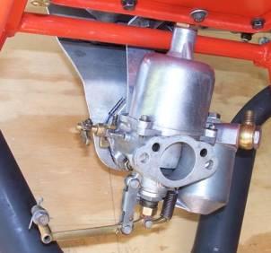
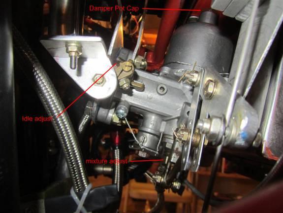
There is very little to do to “tune” the carburetor.The mixture adjustment should be set to full
lean.The mixture adjustment is a nut
on the bottom of the carb.Full lean is
the nut all the way tight (full up).The needle in the needle valve has been setup to provide rich enough
mixture that the engine will run with it at full lean.The mixture is adjusted while the aircraft
is in use using the mixture control knob.The needle can be adjusted if necessary by putting the needle in a drill
press and dressing it with fine sand paper.360 grit is good for this.Idle
has an idle stop adjustment on the throttle arm.This should be set to give an idle speed between 800 and 1000
RPM.Each annual the carburetor should
be removed and the damping fluid should be topped off.Motor oil is an acceptable damping
fluid.The damp pot is accessed by
removing the brass cap from the top of the carburetor.This cap can not be removed while the
carburetor is installed.
Trailering
The main
wheels are 6’3” between center lines.The outside of the wheel pants are 6’ 10” to clear.
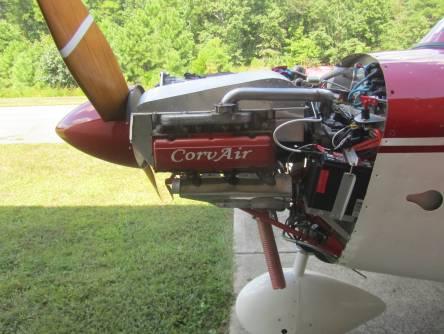
The cowling has 3 quick access covers that are fastened with
a spring fastener.Slide the knob back
to open.
1.Belt Inspection Cover, On the pilots side allows quick access
to the alternator belt to check for tightness and condition.This can also be used to access the battery
for charging.
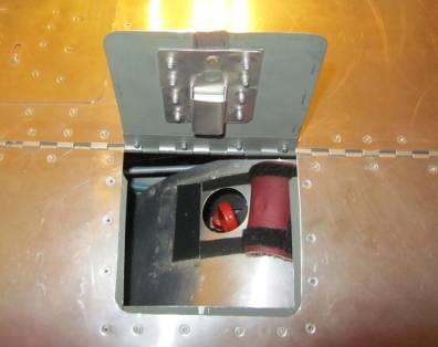
2.Oil Level Cover, on the passenger side, pull the knob back,
lift the cover, then peal back the leather baffling cover to access the oil dip
stick.
3.Oil
Fill Access Cover, in the center of the cowling, to add oil.Also provides access for visible inspection
of the distributor.
Dipstick
Access Cover
The cowling is designed to allow various options for access
for firewall forward maintenance.
By removing 6 screws from the bottom air scoop you gain
access for draining the oil, and checking the air filter.
The following items can be maintained by removing the
camlocks along the hinged cover on the pilot’s side:
·Alternator
and Belt
·Coils
and Condensers
·Coil
Selector
·Oil
Pressure Sensor
The following items can be maintained by removing the
camlocks along the hinged cover on the passenger side.
Distributor
Oil
Air Seperator and Hoses
The following items can be maintained by removing the
pilot’s side cowling side cover by removing (?number?) screws holding it in
place:
Carburetor
Heat Muff and SCAT Ducting
Battery
and Cables
Carburetor
Heat Box and Cable
Battery
and Cables
Pilot
Side Muffler
The following items can be accessed by removing the
passenger side cowling side cover by removing the (?number?) screws holding it
in place:
Cabin
Heat Heat Muff and SCAT Ducting
Passenger
Side Muffler
Mixture
Linkage and Cable
Throttle
Linkage and Cable
For maintenance of the starter it is necessary to remove top
of the cowling.This requires that the
sides be in place and the camlocks on both sides are withdrawn.
For greatest access to the firewall forward/engine area the
entire cowl can be removed.
This inspection is to be conducted at 100 hour flight time
intervals or 2 months which ever comes first.Flight operations should not be continued if until this inspection is
conducted after one of these periods has expired.
The inspection is to include everything mentioned in the
preflight inspection plus the following items.
1.Cable Tensions is to be measured, and if outside of spec
adjusted.Note: rudder tension to be
checked with front of aircraft jacked so that no weight is on the nose wheel.
2.Tire condition to be assessed.If tread is worn completely off in any area the tires are to
replaced.
3.Tire pressure is to be measured and adjusted.
4.Wheels are to be jacked off the ground and wheel bearing play
to be checked.
5.Wing to center carry though nut witness marks are to be
inspected.
6.All control surfaces are to be inspected.
7.All control cable connections are to be inspected for
looseness and or damage.
8.Pito, and Angle of attack probes are to be inspected and
checked for proper operation.
9.Brake level checked and test for air in the brake lines.
This inspection is to be the most comprehensive
performed.All steps in preflight
inspection and 100 hour inspection are to be conducted at this time.All steps are to be recorded in a
maintenance log book, either hard copy or electronic.In addition to the steps outlined in the other inspections the
following inspections are to be conducted.
1.All maintenance covers are to be removed.
2.Fuel is to be drained and filter screens removed.
3.Fuel bowl on gascolator is to be removed and checked.
4.Airframe it to be thoroughly checked for signs of cracks or
smoking rivets.
5.Wiring is to be inspected for signs of chafing.
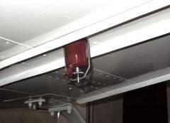
6.Replace the batteries in the ELT.
7.Motor mount is to be thoroughly inspected for cracks.
8.Motor mount to airframe brackets are to be checked for cracks.
9.Canopy condition is to be assessed.
10.Landing gear is to be thoroughly inspected for damage.
11.Condition of the bungy cord is to be assessed.
12.Bungy to be replaced if older than TBD
years or any signs of fraying are evident.
13.Every other annual inspections to include a transponder calibration
check.
14.All hardware is to be inspected for tightness.Torque to be checked and witness marks to be
applied where missing.
The engine is a custom built conversion starting from a 1967
Corvair automobile engine but converted for aircraft use.Most of the core components can be purchased
from Clarke’s Corvair at www.corvair.com.
The engine block is T091RH.This was originally a 110 HP Corvair engine with automatic transmission.
The engine has the following modifications.
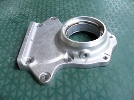
A fifth main bearing.The bearing housing from Dan Wessman www.flyfifthbearing.comreplaces the original bell housing.
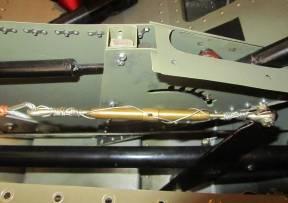
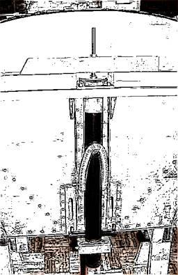
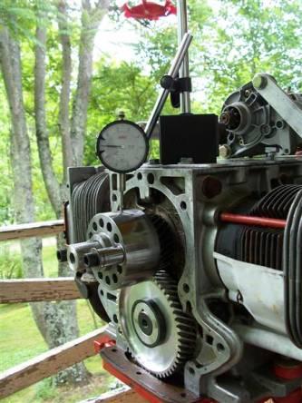
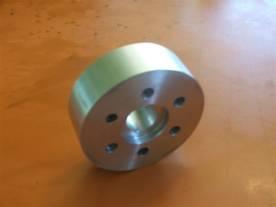
A crank extension has been machined to fit the bearing
provided in Dan Wessman’s housing.This
is a custom made part.
The picture above shows the crank shaft extension while
checking it for run out.
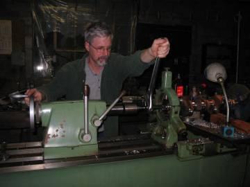
Crank modified by having the end bore threaded to 1-14 SAE.
Above is a picture of the crank being threaded for a safety
shaft.
The crank end seal threads have been enlarged to 3/8-24 SAE.
A special drill guide was made for resizing the tapped holes
in the crank end.There is a pilot on
the guide that fits snug on the end of the crank.
Pistons have been replaced with forged pistons from Clarke’s
Corvair.
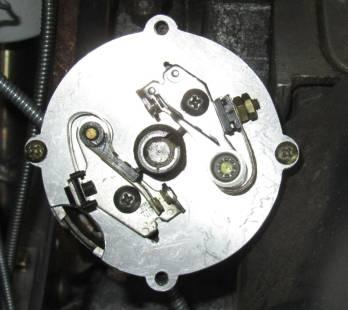
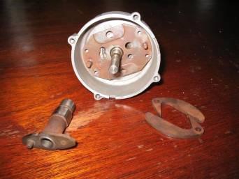
The distributor has been modified to contain 2 sets of
points.
The distributor has also been modified to allow 35 degrees
of advance timing.
It uses light weight springs from an advance curve kit from
Summit Racing #SUM-G5212.
Lighter advance timing springs have been used so that the
engine can reach 35 degrees advance at 2800 RPM.
The CAM has been replaced with an O-20 CAM to move the
engines HP curve to achieve top HP at 3000 instead of 4000 RPM.
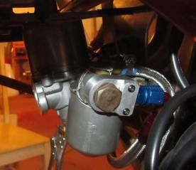
The carburetor have been moved under the oil pan from the
original top mounted position.
The dual carburetors have been replaced with a single SU
carburetor from a 1959 MGA.
The carburetor adapter is banjo type 16 MM to AN-6
custom-made adapter.
The intake manifolds are custom made.
The exhaust manifolds and mufflers are custom made.
The air ducting is custom made and joined together by 2”
SCAT tubing.This is a heat resistant
flexible type of tubing.These are
fastened with 2” stainless steel hose clamps.
All other parts are standard, and replacement parts are
available at Clarke’s Corvair. http://www.corvair.com/
Exhaust gasket between heads and manifold is standard
Corvair.
Exhaust gasket between manifold and muffler is Part #
3631-VW from M & T MFG, at www.mtmgf.com.I also have EMPI Part No 00-3631-0 recorded
as a part no for these.
Exhaust flange is a 2 hole 1.5 ID also from M&T MFG.
Custom Mufflers are held onto the exhaust manifold with 5/16
Brass Exhaust Nuts from Aircraft Spruce, Part No. 22022
Oil Filter is from Clarke’s Corvair, part number C47C.
Mains
are Matco 5” Wheel and brake assembly, Part No. 128244, from Aircraft
Spruce.
Main
wheel axel is 1.25 Dia Matco, Part No.128145 from Aircraft Spruce.
Nose
wheel is a Matco 128272, Cat No NW51CC 75, from Aircraft Spruce.Supplier Aircraft Spruce, Part No.
06-00441, Catalog # 10535-1
Nose
wheel axel is Matco Axel Assembly Part No (06-00536), cat no. 128271
from Aircraft Spruce.
Tires
Good
Year FLT Spec 500-5 6 ply
Tubes
Leak-Guard
500x5, part no 06-00755, from Aircraft Spruce.
Spinner
Van’s
13” Spinner with 2 bulkheads.
Gascolator
Gasket
1053501
From Aircraft Spruce, Part No. 06-00441.
Canopy
Custom
Made from Todd’s Canopy for a Zenith CH 601XL.
Brake Master
Cylinders
MC-5 Vertical Mount Brake Cylinder
Brake Slave
Cylinders
Brake Disks
Brake Pads
Landing
Gear
Supplier:
Aircraft Spruce, Manufactured by ComLet, Part No. 05-02457, Catalog Number
NK093a-550.The undercarriage of the
aircraft was beefed up and custom modified for this installation.
(Here list
the hardware that will likely have to get replaced as things ware and are
screws get lost, especially the little screws that hold down cover plates)